2. Unboxing and Assembly#
This step takes approximately 5 minutes.
2.1 Component List#
Please refer to the Component List to verify all components are present before assembly:
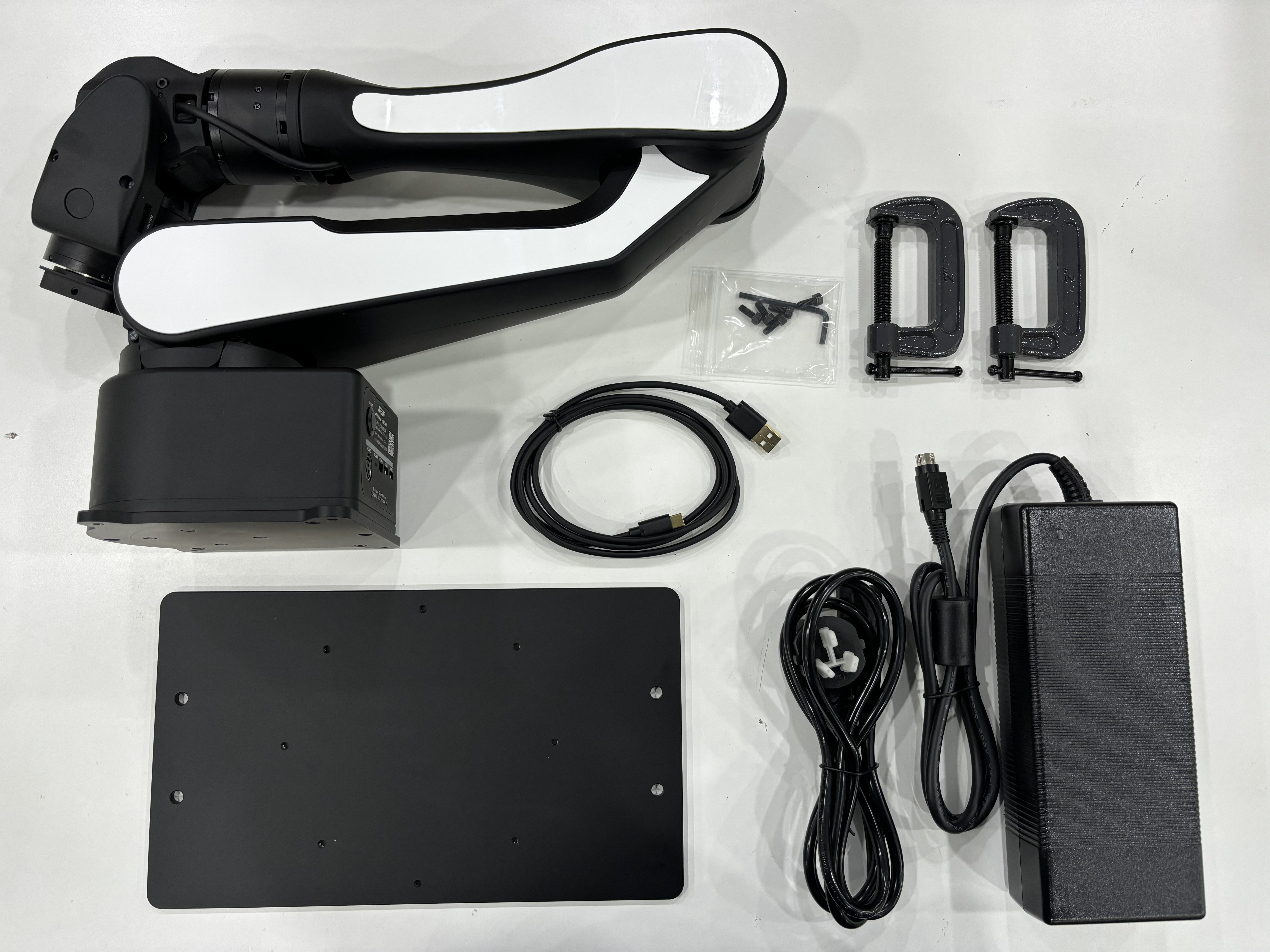
| Item No. | Description | Qty / Unit | Remarks |
|---|---|---|---|
| 1 | AIRBOT Play Robotic Arm | 1 pc | End-effector mounting flange included |
| 2 | Mounting Base Plate | 1 pc | |
| 3 | Desktop Clamp | 2 pcs | |
| 4 | USB Cable | 1 pc | For connection between the arm’s control box and the PC |
| 5 | Power Adapter | 1 pc | |
| 6 | Power Cord | 1 pc | |
| 7 | Screws & L-shaped Hex Key | 1 kit | M3 |
| 8 | Teaching Gripper | 1 set | Optional; cable included |
| 9 | Gripper | 1 set | Optional; cable included |
2.2 Mounting & Securing the Robot Arm#
Note
Always allow adequate clearance around the arm before powering it on; unexpected motion could strike people or nearby objects.
- Take out the arm, mounting base plate, four M4 screws and the L-shaped M4 hex key supplied.
- The robot arm base is secured with screws. Using the supplied mounting plate, you can fasten the arm to the edge of a table: first clamp the plate to the desktop with the two provided desk clamps, then fix the arm to the plate with four M4×10 mm screws. The arm can be oriented horizontally, at a 45° angle, or vertically to suit your application.

- To mount the arm on a third-party fixture, use the mounting-plate hole pattern to design a custom adapter.

2.3 End-Effector Installation [Optional Accessories]#
AIRBOT Play supports two factory end effectors. The arm can be powered on and used with or without any tool attached:
AIRBOT Gripper 2: Parallel Motorized Gripper, codeG2, The standard end-effector for AIRBOT Play. Motor-driven opening and closing.AIRBOT Encoder 2: Motorized Teaching Gripper, codeE2, The default teaching gripper. Its motor-driven fingers generate motion commands to control an external Parallel Motorized Gripper.
-

AIRBOT G2 Parallel Motorized Gripper -

AIRBOT E2 Motorized Teaching Gripper
Other end-effector support
AIRBOT Play also accepts dexterous hands or user-built grippers. Contact technical support for integration help.
Camera support
To mount a camera bracket, place it between the built-in mounting flange and the gripper. For brackets and drawings, please contact technical support.
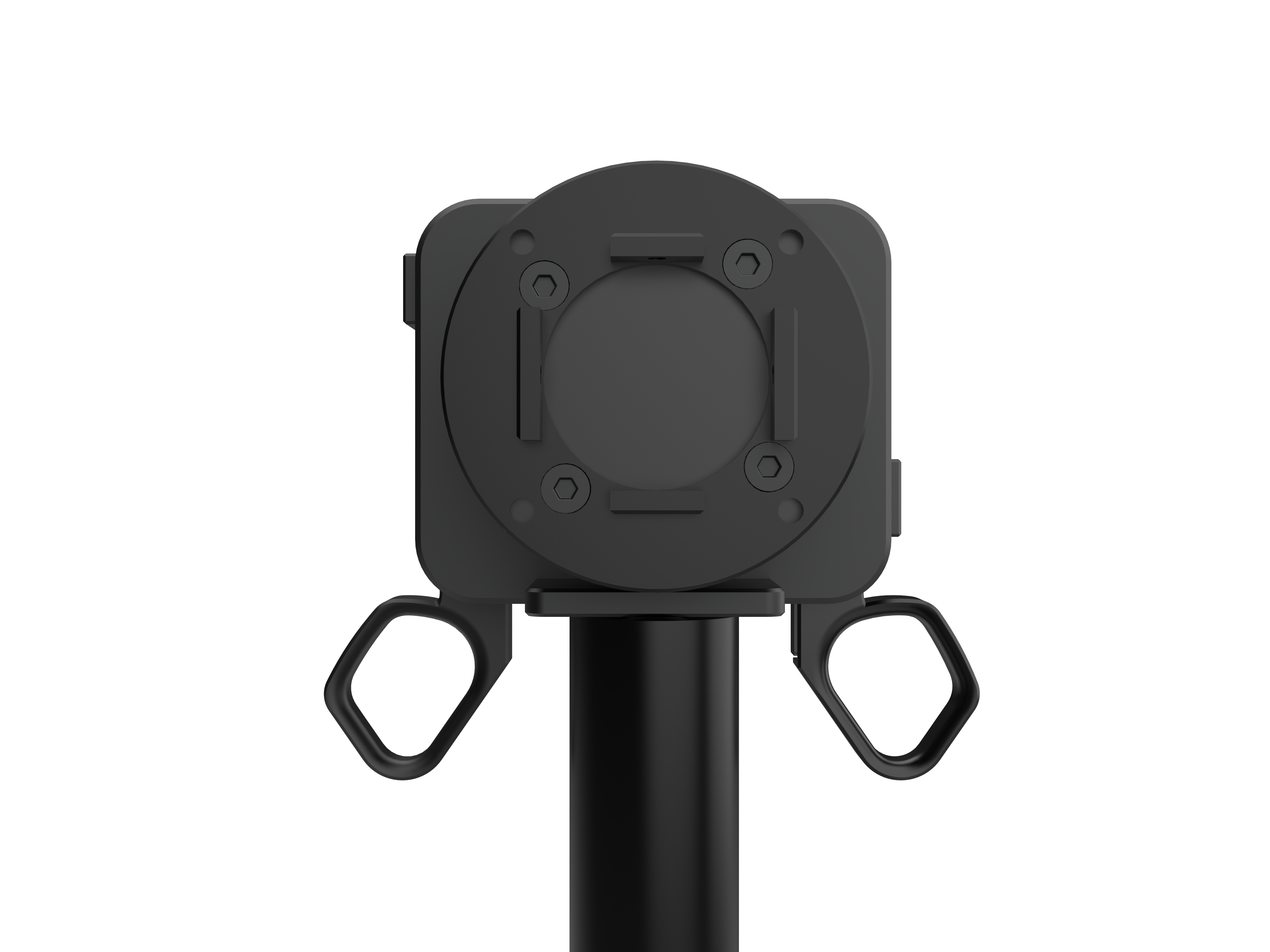
Installation Preparation: The end-effector mounting flange is factory-installed. Before fitting any gripper:
-
Rotate the wrist until the user-button side faces downward.
-
Turn the flange so the teardrop limit boss points downward (see image below).

Correct flange orientation
-
Gripper Installation
Required items: gripper, 4 × M3 screws (supplied). Below are the gripper’s fastening points. Insert it into the arm’s end-effector mounting flange and secure it from the side holes.

Gripper Motor Screw Location Diagram 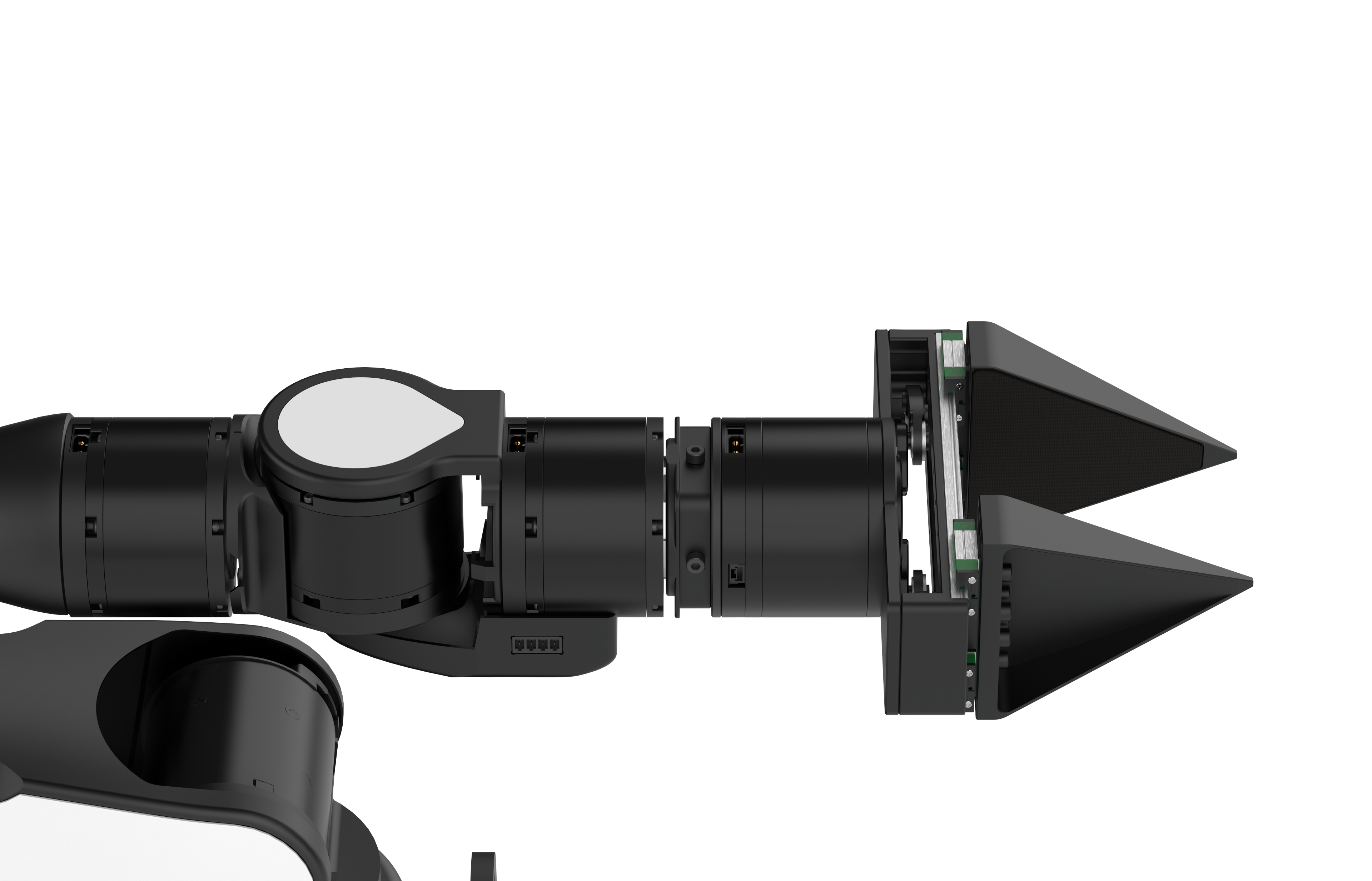
Gripper Screw Location Diagram Take out the supplied gripper cable.
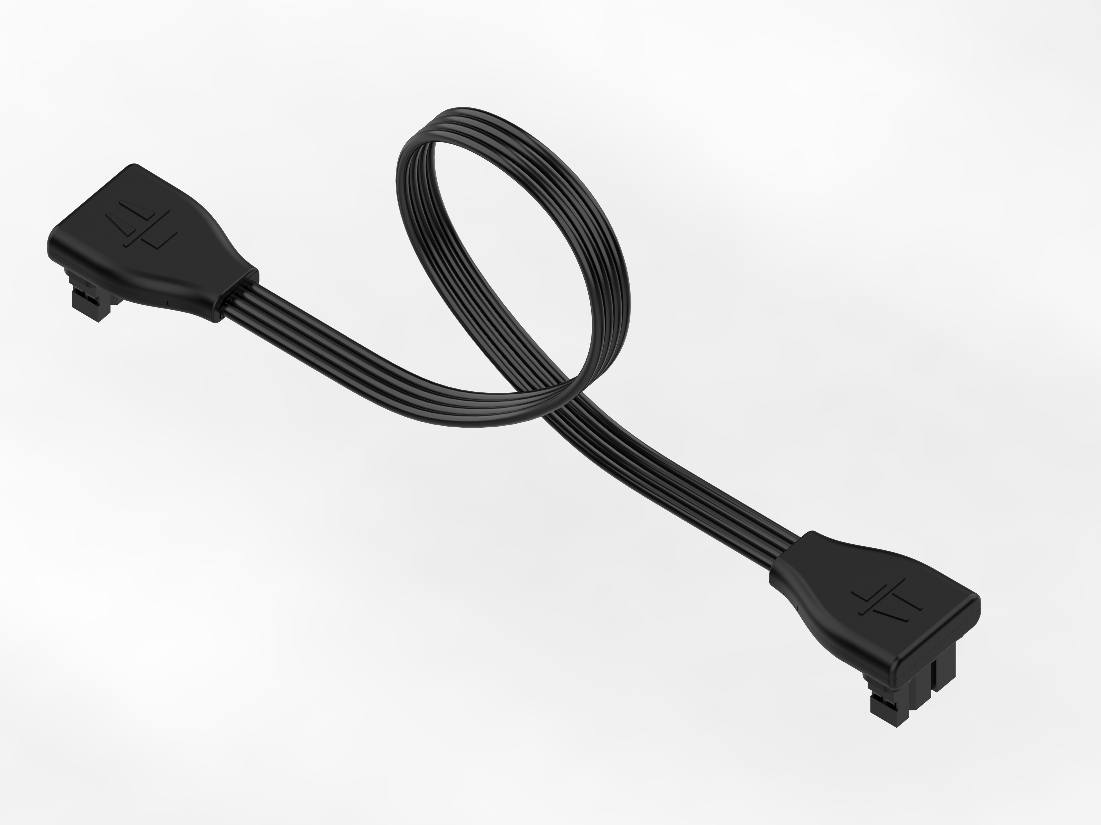
Gripper Cable Connect the cable to the socket shown below.
Note
- Use the cable label to distinguish the gripper lead from the teaching-gripper lead;
- Connect only to the J6 joint socket indicated. Do not connect to any other motor port;
- Do not pull on the wire—this may cause poor contact. Always grip both connector ends when plugging or unplugging.
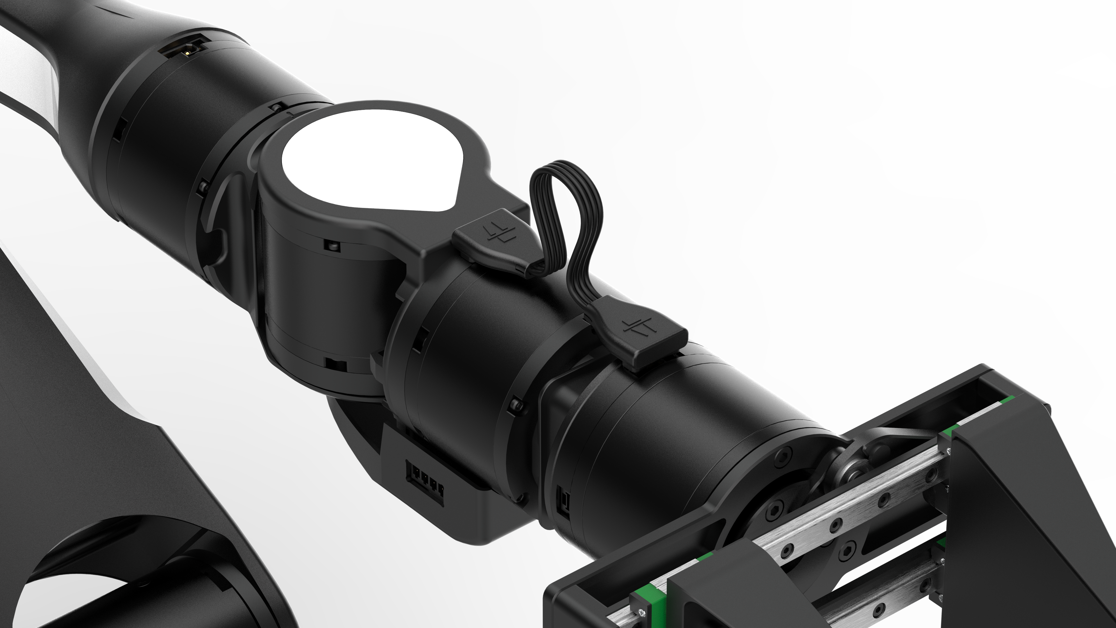
Figure 2.13 Gripper Installed View -
Teaching-Gripper Installation
Required items: teaching gripper, 4 × M3 screws (supplied) Below are the fastening points. Insert the gripper into the arm's end-effector mounting flange and secure it through the side holes.
Teaching-Gripper Motor Screw Location Diagram 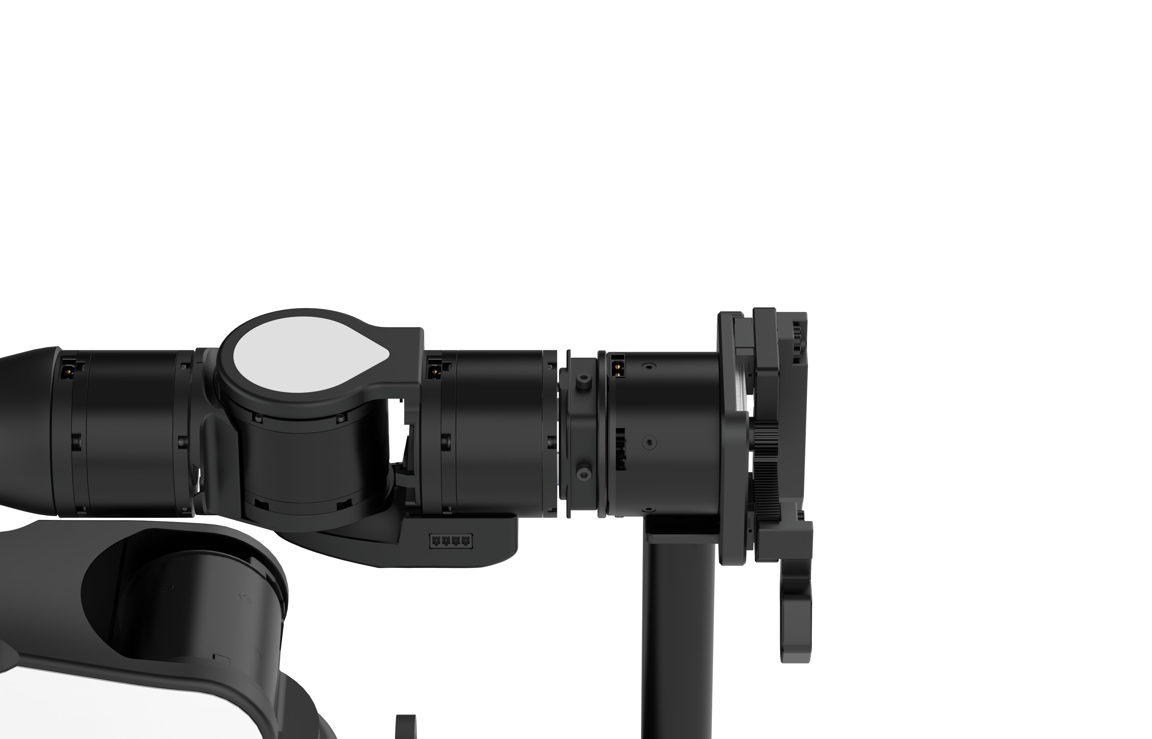
Teaching-Gripper Screw Location Diagram Take out the supplied teaching-gripper cable.
Teaching-Gripper Cable Connect the cable to the socket shown below.
Note
- Use the cable label to distinguish the gripper lead from the teaching-gripper lead;
- Connect only to the J6 joint socket indicated. Do not connect to any other motor port;
- Do not pull on the wire—this may cause poor contact. Always grip both connector ends when plugging or unplugging.
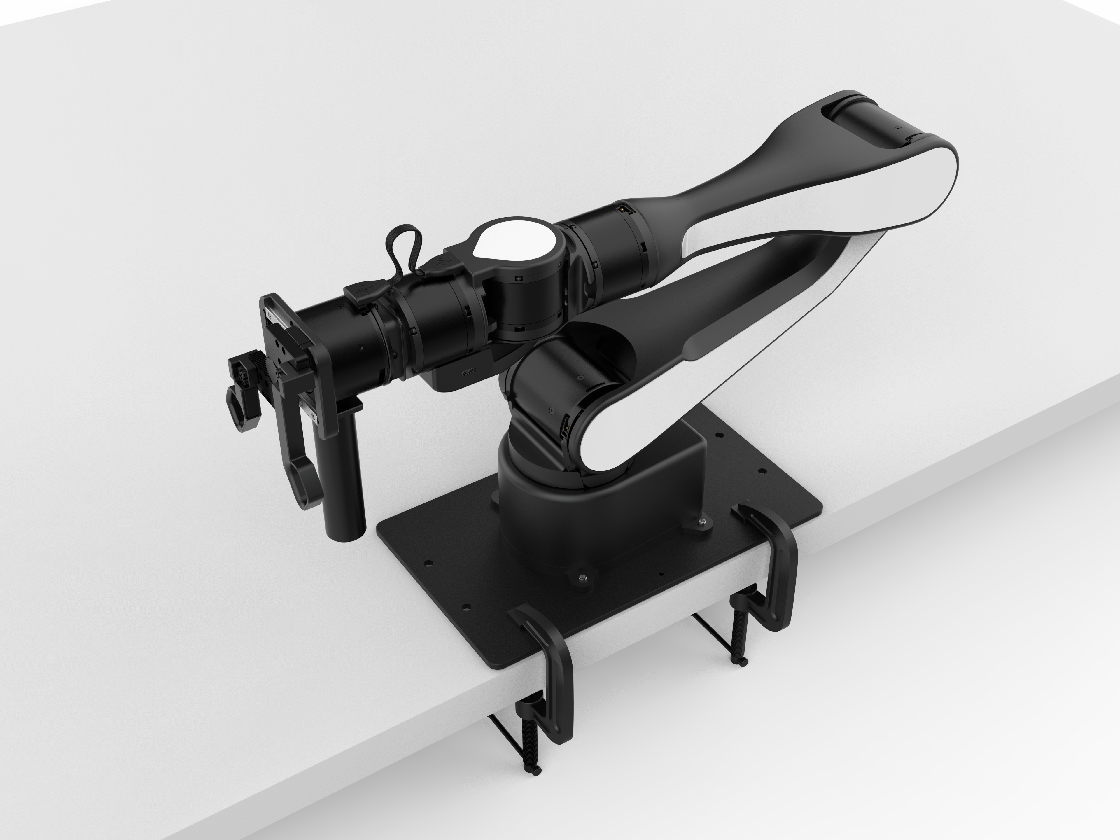
Figure 2.13 Teaching-Gripper Installed View
2.4 Base Connection#
The base-panel interfaces are shown below:

-
Power Port: Connects the arm’s power cable via the aviation plug output from the power adapter.
Note
1.Connect the power adapter to the power cord; push the mating connectors firmly until fully seated to ensure a tight fit.
2.Connect the aviation plug of the power adapter to the power inlet on the AIRBOT robot Base Board, ensuring the black flat side of the plug faces downward.

-
Signal Interfaces: For connecting signal cables.
USB
-
USB-1 (TypeC) delivers end-camera data to the host for end-effector vision-sensor transmission.
-
USB-2 (TypeC) connects the arm to the host via USB for data transfer and control.
-
The recommended wiring is shown below. Once the signal cable is properly connected, the status bar pulses white. After the driver service is starte Driver Service, the bar turns green and the arm becomes ready for PC control.

-
Once these steps are completed and the latest arm software package has been installed on your Linux system Software Setup(see Software Setup), your AIRBOT Play robot arm is ready to run.